7.5. Periodic planes
In currently used approaches, both in the standard methods as well as in the BSDF-based methods, the surrounding objects of glazings, e.g. frames or rails for the shadings, are usually neglected. This can, on the one hand, lead to significant inaccuracies, but on the other hand, provides results of a more general nature, i.e. the results can later be used to model glazings of any size.
In order to be able to perform such calculations efficiently with the RadiCal method, a periodic-plane feature is implemented. Up to two sets of parallel planes can be included in the CAD drawing and defined as periodic planes. Each plane has a front and back side, defined by its surface normal vectors. Any rays intersecting these planes from the front side are relocated to the corresponding, opposite plane. All translations are performed parallel to the specified axis, i.e. two coordinates are held constant. Rays that reach the plane coming from the backside are not affected.
This concept allows for efficient modelling of periodic elements, as only a single element (or any multiple) has to be modelled, provided it is surrounded by periodic planes that correctly reflect the periodic lengths of the structure. E.g. for modelling Venetian blinds (see Figure 100), the vertically aligned planes (Z+, Z-) have to be placed precisely at a distance matching the slat distances, while any distance can be chosen for the horizontally aligned periodic planes (X+,X-).
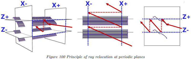
The concept of periodic planes can either be used to model “quasi-homogeneous” surfaces, e.g. glazings shaded by Venetian blinds, as shown in the example in Figure 100, or – more generally – to model structures that are composed of periodic structures, e.g. curtain wall façades or photovoltaic arrays.