Light-matter interaction overview
4.3.1. Scattering
When light, being an electromagnetic wave, reaches or penetrates matter, it starts to interact with the electrical charges of the material. The electromagnetic wave induces dipoles which reradiate an electromagnetic field. The induced field, or secondary wave, superposes with the incident field. Depending on the strength of the interaction and its geometry, the superposition of the fields will cause either reflection, transmission (and refraction) or diffraction of the incident light. Therefore, the most general definition of scattering is a redirection of light that is not absorbed. This definition, of course, includes the effects of refraction and reflection on surfaces. However, the term is often used to only refer to the processes that cause a redirection of light when

it passes through a medium. The most important cases for this type of scattering are referred to asMie- and Rayleigh-scattering.
Rayleigh scattering occurs when light is scattered on particles that are significantly smaller than itswavelength. In this case, light is scattered equally in forward- and backward directions. Due to thestrong inverse wavelength dependence (𝐼 ∝ 1 4⁄ ), Rayleigh scattering is responsible for the blueappearance of the sky but also for the red, yellow and violet colours frequently visible in the sky andclouds, mainly during sunset and sunrise.
Mie scattering occurs when light is scattered on particles having a size close to its wavelength. UnlikeRayleigh scattering, Mie scattering shows dominant forward scattering characteristics and has onlya limited wavelength dependence. As the dimensions of water droplets are roughly in the range ofthe visible light wavelengths, Mie scattering occurs there. Due to the limited wavelength dependence,all colours of the visible light spectrum are scattered equally; therefore, clouds usually appear whiteor grey.
Since the size of the scattering particle relative to the wavelength is relevant, it is helpful to definea non-dimensional size parameter 𝑥 to determine the effective scattering mechanism. For sphericalparticles with radius r, this can simply be defined as (Petty, 2006):

An overview of the relevance of the differenz scattering regimes based on this relation is providedin Figure 18.
4.3.2. Specular reflection
If the incident light interacts with electrons that are relatively free to move, e.g. with unbound electrons in a metal, the electrons will begin to oscillate with a phase difference of 180°, inducing a secondary field. The interference of the incoming light with this secondary field will cause the extinction of the transmitted field and cause a distinct reflection of the incoming light on the surface. Following geometric considerations, it can be shown that the outgoing radiation will leave the surface at the same angle as the incidence occurred. This results in the law of reflection which states that the angle of incidence equals the angle of reflection. Consequently, pronounced specular reflections can be found mainly on the smooth (flat) surfaces of metals or glass. However, there is an important exemption to that rule, as many rough surfaces will exhibit specular reflections for higher incidence angles, known as gloss. A commonly known case is the reflection of sunlight on the rough street pavement close to sunset or sunrise. As a simple explanation, it can be stated that the “effective roughness” of the surface, “seen” from the incident light, decreases with higher angles of incidence for some surface topologies.
While the intensity of the specular reflection is determined by the Fresnel coefficients (see section 4.7), the law of reflection has to be applied to determine the outgoing vector 𝑣 𝑜 of the incoming vector 𝑣 𝑖 and the surface normal 𝑛⃗ . Simple vector algebra can be used to derive a computationally very efficient relation. It can easily be comprehended if the tangential (𝑣 𝑖,𝑡) and normal component (𝑣 𝑖,𝑛) of the incoming vector is considered:

No additional nomalisation is required if the incoming vector is nomalised. This means that the algorithm is very efficient, as only a few basic arithmetic operations are required.
4.3.3. Diffuse reflection
The visible appearance of most objects is dominated by the diffuse reflection of light from their surfaces. While specular reflection relies on the fact that the secondary emitters are regularly aligned so that the induced radiation forms distinct interference patterns with the incident radiation, diffuse reflection represents the more general case of randomly arranged oscillators. The irregularity of the material can either be caused by a rough surface topology or by microscopic irregularities inside the material if the light is able to penetrate below the surface. The latter case is also known as subsurface scattering. It is the relevant mecha

nism to describe how paints work: generally, paint is formed of a binder containing microscopic pigments. The binder usually has a low index of refraction to allow light penetration below the surface. The randomly arranged pigments in the binder usually have higher refractive indices in specific wavelength ranges and scatter the incoming radiation in all directions. Usually, multiple scatterings will occur within the paint layer so that the direction of the light exiting the surface is randomly distributed. Corresponding to the random orientation of the directions, also the polarisation axis of the reflected wave trains are randomly oriented so that diffusely reflected light is largely unpolarised. Diffuse reflection usually is accompanied by specular reflection. While the specular reflection occurs in the uppermost regions of the binder or on additional coating layers, the diffuse reflection occurs on the submerged pigments. This behaviour can be modelled in the RadiCal method (see Figure 104).
The specular reflections on the binder or coatings are usually not spectrally selective. This means that all colours are reflected with almost equal intensity. In sharp contrast, many pigments exhibit a pronounced spectrally selective behaviour. The combination of the “colourful” specular reflection and “monochromatic” diffuse reflection can be seen in the photo depicted in Figure 19. As discussed in section 4.2.4, a polarisation filter can be used to suppress the specular reflection, whereas the mainly unpolarised diffuse reflection will remain unaffected.
4.3.3.1. Lambert reflectance
The Lambertian model is a practically relevant and commonly used definition for an ideal diffusely reflecting surface. It represents the case in which the reflectance of a surface is constant for any given incidence and reflectance angle, implying that objects with Lambertian surfaces appear equally bright from all viewing angles. This is a good approximation for many surfaces and allows a significant level of simplification in many optical models. The characteristics of a Lambertian surface can be shown by deriving the corresponding bi-directional reflectance distribution (BRDF) function 𝑓𝑟 of the hemispherical-directional reflectance 𝜌𝑑, commonly also defined as the albedo of a surface. 𝜌𝑑 is defined as the fraction of light scattered into a direction by a surface illuminated uniformly by hemispheric light (or vice versa):

Since 𝑓𝑟 = 𝑐𝑜𝑛𝑠𝑡. is demanded, the term can be excluded from the integration so that only the product of the incoming direction with the surface normal vector has to be integrated over the hemisphere.

The constant BRDF function of any Lambertian surface can, therefore, be found by dividing its albedo by 𝜋.
4.3.4. Refraction
Refraction represents the change in direction that a light wave suffers on a boundary between two media with different indices of refraction. Since the refraction index measures the slowing of the phase speed of light in a medium, refraction can be explained using the Huygens-Fresnel principle, in which the wavefronts of light are described as a superposition of spherical wavelets.
Figure 20 illustrates how the slower propagation speed (i.e. higher index of refraction) in the second medium will

cause the refracted beam to bend towards the surface normal. The same effect can be observed at beaches where the slower speed of waves in the shallow water will cause a swing of the wavefront towards the shoreline so that the waves will mostly reach them at a perpendicular angle. Snell’s law defines the ratio of the angle of incidence to the angle of refraction:

For polychromatic light, refraction usually leads to a separation of colours as the refraction index is generally a function of wavelength. Typically, shorter wavelengths will suffer stronger refraction. Based on equation (18), it can be seen that the transmitted beam will be refracted towards the surface normal. If, in contrast, the incidence medium is optically denser (𝑛1 > 𝑛2) the transmitted beam will be refracted away from the surface normal. Consequently, there is a critical angle 𝜃𝑐 at which 𝜃2 will reach 90°. At this angle, the transmitted beam will vanish, and all energy will be reflected off the interface.

This case is referred to as total internal reflection. Although the reflection behaviour changes here, total internal reflection does not represent a discontinuity, as the intensity of the transmitted beam decreases continuously with the angle to reach 0 at the critical angle. For a more detailed analysis of refraction and reflection at interfaces, it is necessary to consider the polarisation state of light, as well as the intensities of the beam components. A comprehensive model covering these aspects implicitly has been implemented in the RadiCal method and is presented in detail in section 4.7.
4.3.5. Diffraction
Similar to the case of refraction, the effect of diffraction can be explained using the Huygens-Fresnel principle. However, diffraction occurs in the same medium if a light wave passes nearby an obstacle. Diffraction will affect the linear propagation of light and generally causes a bending of the light beam around a barrier. Figure 21 shows how the bending effect can be explained based on the superposition of wavefronts of spherical wavelets. Diffraction cannot easily be integrated into a raytracing process, as it causes a “bending of light rays”, or, respectively, of fractions of it. This is, of course, beyond the scope of geometrical optics, which is based on the linear propagation of light. Diffraction is, therefore, not contained in the RadiCal method. To assess the impact of diffraction or, respectively, its neglect, a short estimation of the diffraction angle for relevant wavelengths and dimensions is provided below.

In order to analyse the impact of diffraction, two different cases have to be distinguished. In the first case, the diffraction caused by a small opening, a hole in 2D or a slit in 1D, is analysed. In the second case, the bending of light around an edge, i.e. the diffraction pattern caused by a semi-infinite screen is investigated (“knife edge diffraction”).
4.3.5.1. Case 1 – Fraunhofer diffraction behind a slit
For this case, the Fraunhofer diffraction model has to be applied, as it describes the far-field diffraction pattern caused by a small finite opening.
In order to estimate the relevance of diffraction, it is sufficient to perform the calculation in one dimension, i.e. for the diffraction at a slit-like opening. The Fraunhofer diffraction model (Hecht, 2015) states that the angular intensity profile of the diffraction pattern behind a slit of dimension 𝑏 can be modelled according to:


While 𝐼(0) is the central intensity and 𝐼() is the oblique intensity, if the dimensionless length measure is defined as

The corresponding intensity profile of the diffraction pattern can be seen in Figure 22. As can be seen, roughly 90% of the total intensity is contained in the central maximum.
In order to obtain a meaningful analysis of the bending angle, an angle is defined at which the intensity drops to half the central intensity value.
Equation (20) is numerically solved for 𝐼 𝐼(0) = 0.5 and substituted into (21) to find that:

Numerical integration of (20) up to reveals that 72% of the total intensity lies within normal incidence and this angle.
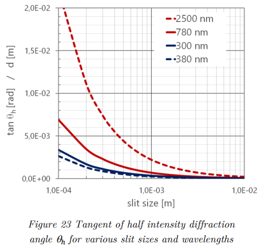
Equation (22) is used to calculate the bending angles for half intensity for different wavelengths and slit sizes. The calculation is performed for the boundary wavelengths of the global radiation spectrum, as well as for the boundaries of the visible spectrum. The tangent of the angles, which, of course, coincides with the deflection 𝑑 of the rays at a distance of 1 m, is depicted in Figure 23. As can be seen for openings of 1 mm, this deflection will range below 1 mm for most of the global radiation spectrum and will only reach 2.2 mm for the longest wavelength of the global radiation spectrum.
4.3.5.2. Case 2 – Fresnel diffraction behind a semi-infinite screen
While the Fresnel diffraction model is usually relevant for the near-field, in close proximity to the obstacle, it can be shown that it is also applicable to determine the diffraction at an edge, as in this case, the dimensions of the opening and screen are (semi-)infinite. The derivation of the relation is elaborate and not covered here; it can be found in (Hecht, 2015). The result of a plane wave hitting an extended obstacle is analysed by calculating the intensity profile behind a semi-infinite screen located in the half-plane 𝑥 ≤ 0. The lights intensity on a screen at a distance 𝑟0 can be described by:


Again, the interference pattern on the screen is calculated for a screen at a distance of 1 m, so that the displacement on the screen corresponds to the tangent of the “bending angle” measured from the Figure 23 Tangent of half intensity diffraction angle ℎ for various slit sizes and wavelengths Figure 24 Intensity profile resulting from diffraction at edge of semi-infite screen at 1 m distance Light, sun and optics – applied principles, models and methods RadiCal, D. Rüdisser 46 edge at 𝑥 = 0. The resulting intensity distribution is again calculated for the boundary wavelengths of the global radiation spectrum. The result is depicted in Figure 24.
As can be seen, a characteristic intensity profile with two specific features develops: Firstly, it is obvious that some light is bent behind the obstacle into the geometrically shaded area (visible at x < 0). Precisely at the edge in between the illuminated and shaded region, the intensity reaches a value 1 4 ⁄ , since the half-amplitude can be expected there. In the illuminated area subsequent to the edge, the intensity rises to reach a maximum value at a distance of approx. 0.5 mm for the UV radiation (300 nm) and approx. 1.5 mm for the infrared radiation (2500 nm). Subsequently, the intensity profile shows oscillations to finally converge to the expected value of 1 for unobstructed light incidence.
4.3.5.3. Coherence considerations
In the two cases evaluated above, coherent superposition of light waves is assumed. As specified in section 4.2.3, sunlight’s temporal and spatial coherence is limited. Hence, the interference patterns of both cases will usually not fully develop as presented in the above charts when sunlight is being used as the source. While the effect can be observed, see, e.g., Greco et al. (1997), it is usually limited to minimal angles or induced by very small openings only. Divitt et al. (2015) have empirically shown that due to the limited spatial coherence of sunlight, strongly developed interference effects can only be observed for slit distances in the range of a few micrometres and below.
4.3.5.4. Supposed diffraction
Many of the observed optical effects in which small openings (e.g. keyholes) cause significantly broadened light beams are attributed to light diffraction, even in scientific literature. A typical example is shown in Figure 25- In fact, these effects are merely caused by the spatial extension of the sun. The angular solar diameter of 0.5 degrees will cause a beam broadening of 3.5 cm on a perpendicularly oriented screen at a distance of 4 m and significantly larger values on any tilted screen. Complementary, the extended blurry edge of shadows is a consequence of this effect and is as well not related to diffraction. The observation that no particular colouring effect is visible in these blurry edges further supports this: as can be seen in the two cases above, diffraction strongly depends on wavelength; consequently, real diffraction of sunlight will lead to a dispersive effect and, hence, usually result in a colourful appearance (see Figure 26).


4.3.5.5. Conclusions regarding the consideration of diffraction
For light with wavelengths in the range of the global radiation spectrum, “bending effects” caused by diffraction at openings larger than approx. 1 mm are weak for coherent light sources (see Figure 23). This is especially true for the shorter wavelengths, which are energetically more relevant (see Table 2). If the limited coherence of sunlight is additionally considered, the relevance of diffraction effects is further reduced. Generally, it is relevant only for openings with dimensions in the micrometre range. The potential level of detail in modelling the raytracing targets will usually not allow a significant number of openings with widths or diameters below 1 mm; however, this will not be relevant for most practical applications.
Textile materials or fine metallic grids might, however, pose a significant exception to this. To overcome this issue, macroscopic surface scattering models, which intrinsically model the microscopic diffraction process, can be developed and implemented in the RadiCal method. Note that even if a significant amount of diffraction starts to occur, the direction of maximum intensity for light passing any one- or two-dimensional openings will still correspond to the central, undeflected path as modelled in the geometrical optics approach. Only the laterally scattered fractions are neglected by the linear model.
4.3.6. Absorption and attenuation
While light propagates through a medium, it can be observed that its intensity decreases along its linear path. The terms extinction and attenuation are usually used to refer to this process; however, the terminology is ambiguous and depends on the scientific subject. The reason for the attenuation of light is twofold. First, the electromagnetic wave interacts with matter and transfers energy to it, known as absorption. Second, light can be partially scattered in the medium due to irregularities in the electromagnetic properties of the medium. The irregularities can be either of microscopic nature with particle sizes below 1µm, e.g. aerosols, or larger, as water droplets in clouds or fat globules in milk (see section 4.3.1).

Apparently, there is a fundamental difference between these two processes, as absorption leads to an actual weakening of the electromagnetic field, whereas pure scattering only redirects fractions of the initial light beam. The reason why both processes are often considered together as attenuation is of empirical nature, as the attenuation of light plays an essential role in spectroscopy or astronomy. In such applications, attenuation is simply a measure of the amount of light emitted by the source but not reaching the detector on a linear path, regardless of whether it is scattered away or absorbed. In this work, only attenuation by absorption is considered. There are two reasons for that: firstly, the effect of scattering is negligible for most materials relevant in building science, while absorption ranges over several orders of magnitude and defines whether the material is transparent, partly transparent or opaque. Secondly, to appropriately consider scattering effects, they have to be integrated into the raytracing algorithm, as the energy of the scattered light is not lost but redirected. Hence, energy conservation can only be ensured if these redirection processes are modelled accordingly. While currently not implemented, the necessary scattering algorithm can quite easily be added in future, again based on the Monte-Carlo approach.
In order to quantify attenuation in a medium, a simple relation can be applied. By observation, Pierre Bouger (1760) and Johann Heinrich Lambert (1760) found that equal parts of the same absorbing medium will absorb equal fractions of light:

After integration, the fundamental equation for absorption is found. It was later formulated by Beer (1852) and is now commonly known as Beer-Lambert or Lambert-Beer-Bourguer law:
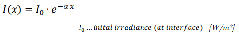
Sometimes the reciprocal value of the attenuation coefficient is used. It is referred to as attenuation length 𝜇 = 1 𝛼 ⁄ and defines the length at which the intensity has decreased to the fraction 1/𝑒 (37%) of the initial intensity (see Figure 27).
If attenuation by absorption is considered only, Beer-Lambert’s law can be derived from an electrodynamic point of view, i.e. by solving Maxwell’s equation for an absorbing medium. This is demonstrated in section 4.6.1. However, looking ahead, the fundamental equation that links the “macroscopic” or empirical quantity attenuation coefficient to the “atomic” extinction coefficient (or imaginary part of the refractive index) is already presented here. Since generally is a function of wavelength, it is stated as:

4.3.7. Thin-films and thick slabs
The term thin-film is generally used to refer to one or more thin, planar and parallel layers in-between two bulk materials, usually air and optically denser material. Typical examples are low-E coatings on glazings, antireflective coatings on sunglasses or oil films on water. The defining characteristic of thin-films is the occurrence of interference effects. The varying refractive indices of the individual layers cause a series of partial reflections at the interfaces. The incoming light is therefore split into multiple paths of light. The superposition of the separate beams determines the thin-film stack’s total transmittance or reflectance. In the thin-film model, it is assumed that

the relevant path differences of the beams range below the coherence length of the light, which is in the range of a few micrometres for sunlight (see section 4.2.3). Hence, models of wave optics that consider the waves’ phases must be applied to model such thin-film stacks (see section 4.7.1.). Since the optical path length relative to the wavelength determines if constructive or destructive interference occurs, thin-films show distinct spectrally selective properties.
In contrast, the thick slab model has to be applied if the thickness of the layer ranges significantly above the coherence length. In this case, individual beams are no longer able to interfere. Hence, the resulting intensities of the transmitted or reflected beams are simply determined by summation of the intensities of the individual beams.
In the field of glazing, which is of particular importance for this work, the determination of thinflims and thick slabs is relatively straightforward. Coatings on glazings usually consist of layers having only a few nanometers of thickness, while thicknesses of typical glass panes are in the range of a few millimetres. Therefore, coatings must be modelled as thin-flims, considering interference effects, while the thick slab model has to be applied for glass panes (see section 4.12).